1. Introduction
In modern buildings, providing a stable and high-quality TV signal is one of the essential needs for every residential unit. Installing individual antennas for each unit not only clutters the rooftop and reduces the building’s aesthetic appeal, but in many cases, the signal quality is also inconsistent. To solve this problem, the Central Antenna System (MATV) was developed—a system that uses a single antenna to receive, amplify, and distribute the signal simultaneously to all units.
The importance of this system becomes even clearer when we realize that the last point of signal reception in each unit is the TV outlet—the module installed inside the switch and socket frame—which plays a crucial role in the final image quality. Understanding the system’s operation and the mechanism of the TV outlet helps us make smarter choices when designing, purchasing, and installing switches and sockets.
2. Main Components of a Central Antenna System
A central antenna system consists of a set of electronic equipment and cables, each with a specific role in receiving, amplifying, and transmitting the signal. Understanding these components is the foundational step in grasping the system’s overall functionality. Below are the most important components:
2.1 Receiving Antenna (UHF / VHF)
The rooftop antenna is the first and most important component of the system.
Functions:
-
Receive TV waves in UHF and VHF bands
-
Convert electromagnetic waves into electrical signals
-
Maintain stable reception even under adverse weather conditions
The antenna’s power and orientation significantly affect the final picture quality in the units.
2.2 Central Amplifier / Booster
The raw signal received by the antenna is usually weak. To prevent quality loss over long distances, an amplifier is used.
Functions:
-
Boost signal strength
-
Reduce noise and interference
-
Adjust output power according to the number of units
In large buildings, multi-stage amplifiers are often used.
2.3 Splitter / Divider
After amplification, the signal must be distributed among the units. A splitter is a passive device that sends the signal to multiple outputs.
Types of Splitters:
-
2-way, 3-way, 4-way, 6-way, 8-way, and more
Important Note: The more outputs, the greater the signal loss.
2.4 Coaxial Cables
These cables are the main path for signal transmission. Cable quality is critical for signal strength and clarity.
Key Features:
-
Standard impedance of 75 ohms
-
Copper or aluminum shielding to prevent noise
-
Stability over long distances
Low-quality cables can cause snow, pixelation, and signal interruptions.
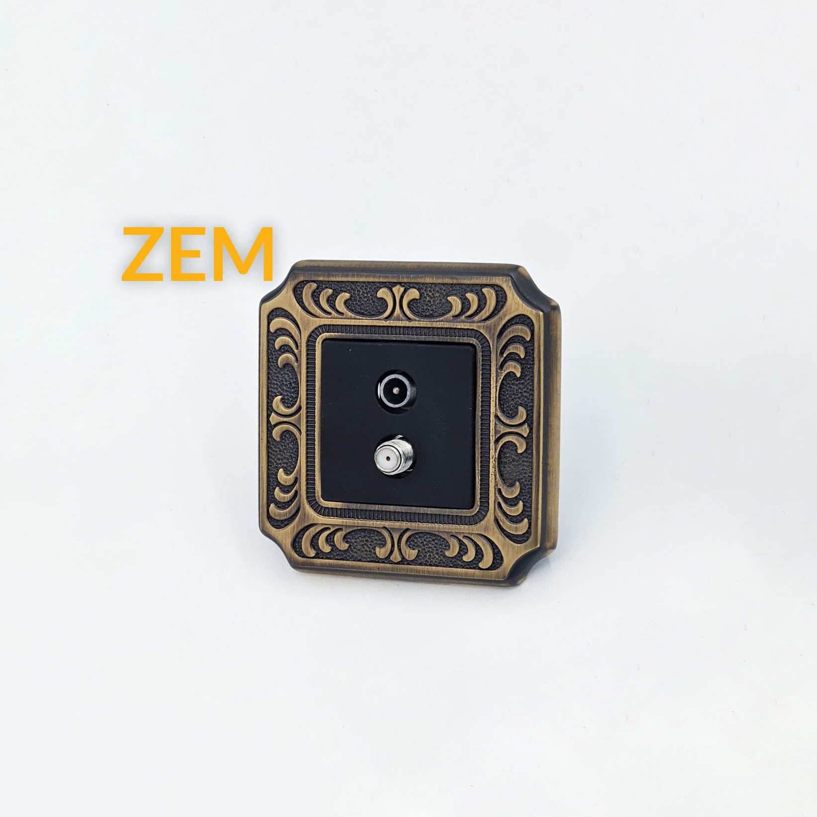
2.5 TV Outlets in Switch and Socket Frames
From the user’s perspective, this is the last and most critical component. This is the point where the TV connects, and a significant portion of image quality is determined here.
Role of the TV outlet:
-
Provide a secure and precise connection of the antenna cable to the TV
-
Prevent signal loss at the final point
-
Control impedance to avoid reflection or noise
We will dedicate a full section to the mechanism of the TV outlet inside the switch and socket frame later.
2.6 Filters and Switchers (Optional)
In professional or large building systems, additional equipment may be included:
-
Channel filters to remove unwanted signals
-
Switchers to manage multiple signal sources
-
Tap-offs for distribution in longer networks
These devices enhance signal quality and stability across the building.
3. How a Central Antenna System Works
The system follows a clear path: it first receives the signal, then amplifies it, and finally distributes it among the units. Let’s break down the process into precise stages:
Stage 1: Signal Reception by Rooftop Antenna
The rooftop antenna receives broadcast TV waves over UHF and VHF bands.
Factors affecting reception quality:
-
Antenna height
-
Orientation and installation angle
-
Distance from the TV transmitter
-
Environmental obstacles (tall buildings, mountains, trees)
-
Antenna quality
At this stage, the received signal is still raw and weak.
Stage 2: Signal Amplification (Booster)
The raw signal enters the amplifier, which:
-
Boosts signal power for long-distance transmission
-
Eliminates additional noise
-
Adjusts output power according to the number of units
-
Prevents signal loss in splitters
In large buildings, multi-stage or line amplifiers may be used. Proper amplification ensures even distant units receive a clear picture.
Stage 3: Signal Distribution (Splitter)
The amplified signal reaches the splitter, which divides it into multiple paths.
Notes:
-
Natural signal loss of 3–10 dB occurs
-
Split paths must be balanced
-
Higher numbers of outputs require stronger amplification
Some projects use multi-stage distribution (e.g., rooftop to floors, then internal division).
Stage 4: Transmission via Coaxial Cables
Cables carry the signal from splitters to units.
Important Points:
-
Low-quality cables result in significant signal loss
-
Sharp bends or pinching reduce image quality
-
Weak shielding allows electromagnetic interference
Stage 5: Signal Reception by TV Outlet
This is the point directly related to switch and socket frames. The TV outlet receives the coaxial cable inside the unit:
-
The TV module receives the signal from the cable
-
Internal circuitry adjusts impedance
-
Standard IEC or F-Type output sends a clean signal to the TV
Even if all previous stages are correctly installed, a low-quality outlet can:
-
Reduce signal strength
-
Introduce noise
-
Cause pixelation
Stage 6: Displaying a Clear Picture on TV
The final result is a stable and clean signal on the TV. The image quality depends on:
-
Antenna reception strength
-
Amplifier performance
-
Splitter quality
-
Cable quality
-
Quality of the TV outlet inside the frame
Any issue in these stages will affect the final display.
4. How the TV Outlet Works Inside Switch and Socket Frames
The TV outlet is the final stage in a central antenna system. Its small module receives the coaxial signal and transmits it to the TV without loss or noise while maintaining standard impedance. Even minor design flaws can disrupt the entire signal chain.
Mechanism Steps:
-
Coaxial Cable Connection
-
Core → Signal path
-
Shield → Ground
Proper connection ensures noise-free transmission.
-
Impedance Matching (75 ohms)
-
Prevents signal reflection
-
Reduces noise and pixelation
-
Internal Filters
-
Pass UHF/VHF frequencies
-
Block unwanted interference
-
Shielded Metal Housing
-
Protects against electromagnetic interference
-
Output Connector (IEC or F-Type)
-
Transfers the signal with minimal loss
-
Maintains high-frequency integrity
-
Installation in Frame
-
Single-module or multi-module configuration
-
Allows easy installation and maintenance
-
Preventing Signal Loss
-
High-quality engineering prevents sudden drops
-
Maintains clear, uninterrupted image
5. Types of TV Outlets and Differences
| Type | Function | Application |
|---|---|---|
| TV | Terrestrial TV only (UHF/VHF) | Standard residential units |
| R/TV | TV + FM Radio | Units with radio reception |
| SAT | Satellite (950–2150 MHz) | Central satellite dishes, SMATV |
| R/TV/SAT | TV + Radio + Satellite | Luxury projects and large complexes |
Through vs Terminal Outlets:
-
Through (Loop) → passes signal to next outlet, used in series/loop systems
-
Terminal (End) → last outlet in line, contains end-line resistor, used in star systems
6. Wiring Methods: Star vs Loop
Star Wiring
-
Each outlet has a dedicated cable from a central splitter
-
Advantages: Excellent signal, adjustable, minimal interference, ideal for luxury projects
-
Works best with terminal TV outlets
Loop/Series Wiring
-
Outlets connected in series
-
Advantages: Lower cable costs, faster installation
-
Disadvantages: Signal loss, interference, dependency between outlets
Comparison Table:
| Feature | Star | Loop |
|---|---|---|
| Signal Quality | Excellent | Medium to low |
| Compatibility with Terminal | Yes | No |
| Compatibility with Through | Rarely | Yes |
| Signal Loss | Minimal | High |
| Noise | Minimal | High |
| Engineering Standard | ✅ | ❌ |
| Luxury Projects | ✅ | ❌ |
| Modern Frame Compatibility | Excellent | Limited |
Best Method for Modern Frames: Star wiring, with terminal outlets, high-quality coaxial, and compatible frames.
7. FAQs – Central Antenna System and TV Outlets
-
What is a central antenna system?
A network that receives TV (UHF/VHF) and satellite signals from a central point and distributes them to all units with minimal noise. -
Difference between Terminal and Loop outlets?
-
Terminal → End of line, contains 75-ohm resistor, used in star systems
-
Loop → Passes signal to the next outlet, used in loop systems
-
Star vs Loop Wiring?
-
Star → Dedicated cable per outlet, minimal loss, low noise
-
Loop → Series connection, high loss, noise-prone
-
Difference between TV, R/TV, R/TV/SAT outlets?
-
TV → Terrestrial only
-
R/TV → TV + FM Radio
-
R/TV/SAT → TV + Radio + Satellite
-
Why might TV signal be poor despite a central system?
-
Poor or long cables
-
Incorrect outlet installation
-
Using loop outlet in star system
-
Low-quality connectors
-
Improper amplifier setting
-
Electromagnetic interference from power cables
-
Coaxial cable requirements:
-
75-ohm impedance
-
Proper shielding
-
Minimal signal loss at high frequencies
-
RG6 or RG11 recommended
-
Does the frame affect signal quality?
No direct effect, but it must be compatible with the mechanism for proper installation. -
How to ensure a proper TV outlet installation?
-
Correct core and shield connection
-
Straight alignment in the box
-
High-quality mechanism
-
Correct type: Terminal for star, Loop for series
-
Clean output without noise
-
Can TV outlet be combined with power outlets in one frame?
Yes, modern multi-module frames allow TV, power, and network outlets together without signal loss. -
Best practice for luxury building central antenna installation:
-
Star wiring
-
Terminal outlet per unit
-
RG6 or RG11 coaxial with full shielding
-
Properly adjusted central amplifier
-
High-quality TV outlet mechanism compatible with interior design

